Technical Support
+3023990 20321
1. MAIN PRINCIPLES
– The ingress of water and water vapor in building materials causes huge damage, namely:
– Erosion and disintegration
– Chemical corrosion and oxidation of the concrete steel reinforcement
– Creation of rashes and spots
– Development of flora, lichen and fungi
Many of these are due to the direct effects of moisture, depending on the natural and chemical properties of water and on the building materials.
Another parameter is the significant increase of the volume of water (10%), because of the effect of frost, from liquid to solid form. The destructive effect of frost, is a function of the porosity of each material and the amount of the absorbed water.
2. THE OCCASSION OF AN UNDERGROUND TANK
– Avoiding leakage from the tank to the environment, ensured by the seal of the tank interior and
– Prevent water inflow to the tank components, ensuring the exterior sealing of the tank (see UNDERGROUND WATERPROOFING). The watertight basin creates a sealed to the entire foundation of the building, up to the ground level.
– In case of underground tank, waterproofing is made from the interior. The waterproofing layer has to be effective in preventing leakage, and it should be able to follow the expansions-contractions of the bottom and walls, which are caused due to exposure of the tank to temperature changes.
– Waterproofing tank by synthetic PVC membrane covers the above needs. In case of a tank of drinking water, the use of special synthetic membrane Flagon AT, 1,5mm thickness is required. Its raw materials allow the final product to come into contact with drinking water without causing adverse consequences.
3. APPLICATION
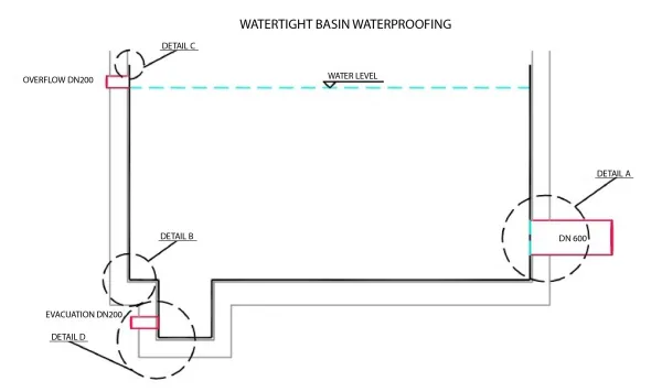
Fig.1 General Layout: Details Α,Β,C,D
– The bottom waterproof is made withfree spreading of Flagon AT and thermal seams with automatic or manual gluing The bottom waterproofing layer is fixed mechanically to the perimeter by strip (Fig. 2).
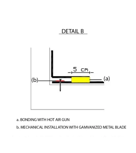
Fig.2
– Vertical elements water proofing is also made by free positioningof rollsof thesynthetic membraneand theiradhesion on stitching is made withhot airmachine. Prior, their mechanicalattachment has been made bymetalorlaminatedblade(Fig. 3), in each caseoverthe output of thesurgetank.
– Followsthethermalfilm which coversthe verticalelements (walls) in that of the bottom, beyond theperimeterof mechanicalbondingof the latter(Fig. 2).
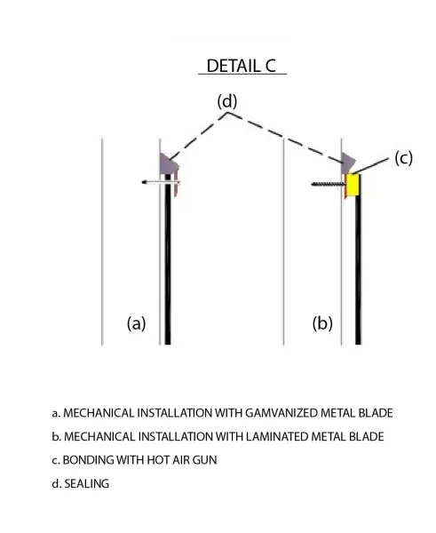
Fig. 3, Detail C
NOTES:
1. Waterproofingat points of entry- exit of metal pipeson the wallsof the tank, is donw as shownin Fig.
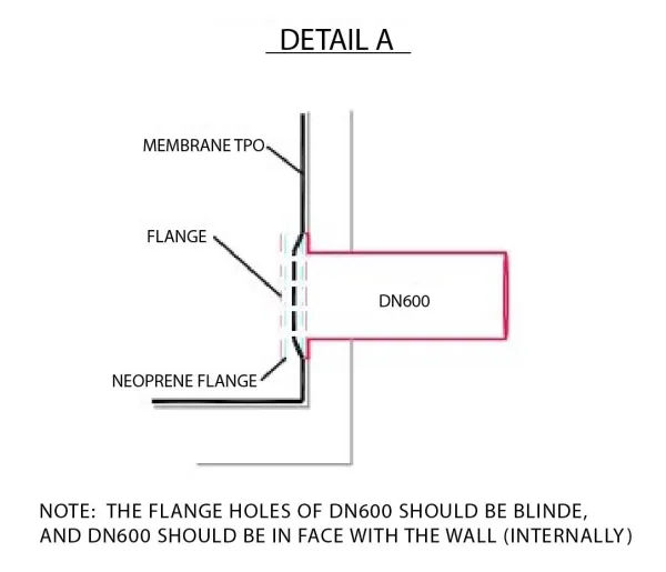
Fig. 4, Detail A
While, the holes in the flanges (metal / neoprene) should be at least in the medium, if not the center of the cross section (Fig. 5).
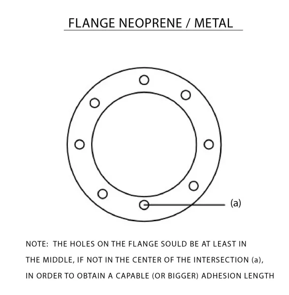
Fig. 5
2. The evacuation of the tank should be as low as possible, considering the construction detail D (Fig. 6).
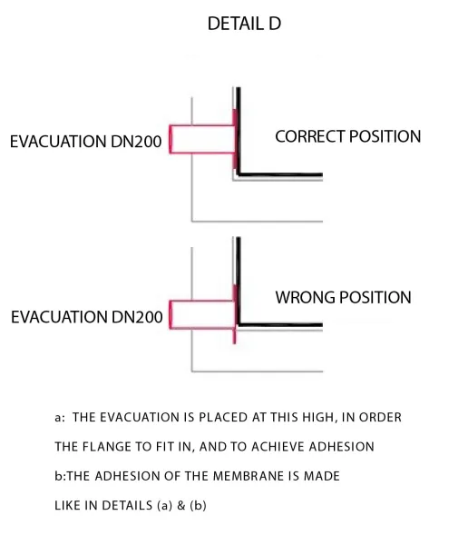
Fig. 6, Detail D
3. In firefighting tanks where the discharge is fast, is recommended the mechanical evacuation of membranes of vertical elements.
The supports are placed at 0.40 – 0.50m, followed by the welding of the seam, beyond the point of mechanical fastening.
4. In any other case (irrigation tank, fire) does not required the use of special synthetic membrane FLAGON AT.
5. Special gutter pieces, of internal & external angle TPO / PVC of the group ETERNO IVICA, facilitate implementation and optimize the final result.